Appunti su ESP8266
URL definizione board per IDE Arduino
http://arduino.esp8266.com/stable/package_esp8266com_index.json
Breakout board implementation
Qui sotto trovate lo schema della breakout board che ho dovuto mettere insieme per cominciare i test:
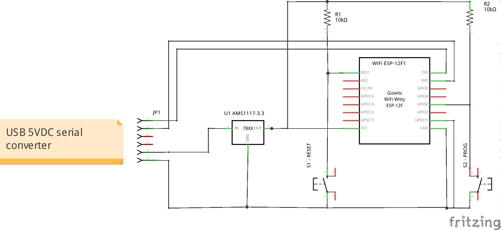
il tasto blu e' reset, il tasto giallo il tasto per iniziare il flashing del software dall'ambiente integrato Arduino.
Alcuni collegamenti che vengono citati da varie fonti non sembrano essere necessari.
In particolare quello suggerito per il piendino 3 (EN o CHPD) non solo non serve ma inibisce il funzionamento del LED blu della scheda.
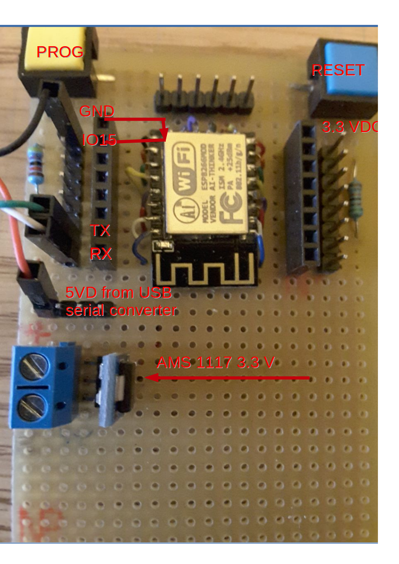
Per l'alimentazione a 5VD ho previsto uno stabilizzatore 5->3.3 e due ingressi per la 5V:
- morsetto per alimentazione esterna, blu nell'immagine
- pin per alimentazione dall' interfaccia USB-seriale codice Acmesystems USB-3V-SER
in convertitore Acmesystems si e' dimostrato in grado di fornire tutta la corrente necessaria al funzionamento del modulo.
Installazione ambiente Arduino
Pur operando su Linux (Ubuntu 14.04) ho seguito queste istruzioni con la ovvia eccezione della parte relativa all'installazione del driver USB che su Linux non serve.
La configurazione dello IDE Arduino e' la seguente:

Scansione reti wireless ricevibili
Il primo programma da usare per verificare il funzionamento del modulo e' l'esempio di scansione delle reti wireless ricevibili. Oltre alla scansione vera e propria contenuta nella procedura loop(), nel setup sono utilizzati alcuni accorgimenti che tornano utili anche nei programmi successivi, in particolare la predisposizione della modalita' STATION (nvece del default che e' STA+AP) e la disconnessione preventiva, necessaria quando in fase di sviluppo si fanno continui riavvi.
void setup() {
  Serial.begin(115200);

  // Set WiFi to station mode and disconnect from an AP if it was previously connected
  WiFi.mode(WIFI_STA);
  WiFi.disconnect();
  delay(100);

  Serial.println("Setup done");
}
la procedura di scansione e' piuttosto banale, si limita ad elencare tutti gli SSID ricevibili, con i vari parametri ed il livello del segnale:
void loop() {
  Serial.println("scan start");

  // WiFi.scanNetworks will return the number of networks found
  int n = WiFi.scanNetworks();
  Serial.print("scan done, ");
  if (n == 0)
    Serial.println("no networks found");
  else
  {
    Serial.print(n);
    Serial.println(" networks found");
    for (int i = 0; i < n; ++i)
    {
      // Print SSID and RSSI for each network found
      Serial.print(i + 1);
      Serial.print(": ");
      Serial.print(WiFi.SSID(i));
      Serial.print(" (");
      Serial.print(WiFi.RSSI(i));
      Serial.print(")");
      Serial.println((WiFi.encryptionType(i) == ENC_TYPE_NONE)?" ":"*");
      delay(10);
    }
  }
  Serial.println("");
Qui vedete un esempio di output mostrato sulla console:
scan start
scan done, 6 networks found
1: FASTWEB-1-XXXXXX (-73)*
2: Meraki33 (-45)*
3: Meraki34 (-43)*
4: Telecom-30203XXX (-56)*
5: FASTWEB (-81)*
6: FASTWEB-1-YYYYYYY (-89)*
l'asterisco finale indica che la rete e' protetta con crittografia e quindi e' necessario fornire in fase di connessione almeno una pre shared key (PSK).
Ping
Per quanto possa sembrare incredibile, il software Arduino per ESP-8266 non fornisce nativamente la funzionalita' di ping, occorre quindi installare un modulo supplementare
Nel programma di esempio occorre modificare almeno tre righe:
- ssid
- password (se la rete e' aperta inserire una stringa vuota)
- l'indirizzo che si vuole pingare (io ho inserito quello di uno dei server Telegram)
#include <ESP8266WiFi.h>
#include <ESP8266Ping.h>

char ssid[] = "SSID";
char password[] = "presharedkey";

const IPAddress remote_ip(149, 154 ,167, 120); // destinazione verso cui indirizzare il PING

int i = 0;

void setup() {
  Serial.begin(115200);
  delay(10);


  // We start by connecting to a WiFi network
  // station mode
  WiFi.mode(WIFI_STA);
  WiFi.disconnect();

  if (strlen(password))
    WiFi.begin(ssid,password);
  else
    WiFi.begin(ssid);


  Serial.println();
  Serial.println("Connecting to WiFi");

  while (WiFi.status() != WL_CONNECTED) {
    delay (1000);

    Serial.print(i);
    Serial.print(": connecting to ");
    Serial.println(ssid);

    Serial.printf("Connection status: %d\n", WiFi.status());
    Serial.println("--------");
    WiFi.printDiag(Serial);
    Serial.printf("\n........\n\n");
    ++i;

  }

  Serial.println();
  Serial.print("WiFi connected with ip ");
  Serial.println(WiFi.localIP());

}

void loop() {

  Serial.print("Pinging ip ");
  Serial.println(remote_ip);

  if(Ping.ping(remote_ip)) {
    Serial.println("Success!!");
    int avg_time_ms = Ping.averageTime();
    Serial.printf("Average time. %d\n", avg_time_ms);
  } else {
    Serial.println("Error :(");
  }

  delay (3000);
}
da notare che le funzioni sia di connessione che di ping sono sincrone, quindi, quando eseguite nella funzione loop(), bloccano il loop medesimo.
Eventi real time devono quindi essere gestiti in background con l'uso di interrupt.
Integrazione con Telegram
Vi sono almeno tre moduli per l'integrazione con Telegram: io ho utilizzato
Questo modulo richiede come prequisito il modulo ArduinoJson scritto Benoît Blanchon. Tutti e due i moduli sono presenti nel Arduino Library manager dell'ambiente integrato e conviene installarli da li', almeno la prima volta.
Nel programma di esempio come output ho scelto di usare il led blu (pin 2), come input il pin 14, che nell'esempio rappresenta il contatto di allarme che proviene da una centralina legacy.
Poichè le funzioni della modulo Telegram sono sincrone, occorre dosare il tempo di polling (vedi variabili Bot_lasttime e alarm_lastime). Con i valori indicati si ottiene un compromesso tra reattivita' e consumo di CPU (e banda Internet).
Il bot e' aperto, chiunque puo' collegarsi conoscendone il nome, quindi, in caso di uso reale, occorre controllare il nome dell'utente e/o lo id della chat.
/*******************************************************************
 *  An example of bot that receives commands and turns on and off  *
 *  an LED.                                                        *
 *                                                                 *
 *  written by Giacarlo Bacchio (Gianbacchio on Github)            *
 *  adapted by Brian Lough                                         *
 *  modified by A.Montefusco IW0HDV                                *
 *                                                                 *
 *                                                                 *
 * https://github.com/witnessmenow/Universal-Arduino-Telegram-Bot/ *
 *                                                                 *
 *******************************************************************/

#include <ESP8266WiFi.h>
#include <WiFiClientSecure.h>
#include <UniversalTelegramBot.h>

const char* ssid     = "YourSSID";
const char* pass     = "YourPSK";

// Initialize Telegram BOT

#define BOTtoken "XXXXXXXXX:YYYYYYYYYYYYYYYYYYYYYYYYYYYYYYYYYYY"  //token of FlashledBOT
#define BOTname "botname"
#define BOTusername "botname_bot"

WiFiClientSecure client;
UniversalTelegramBot bot(BOTtoken, client);

String chat_id;  // initialized upon /start

const int Bot_mtbs = 3000; //mean time between scan messages
long Bot_lasttime;   //last time messages' scan has been done
bool Start = false;

//
// LED management
//
const int pinLed = 2;
bool ledStatus = false;

//
// ALARM MANAGEMENT
//
const int pinIn = 14;
const int alarm_mtbs = 3000; //mean time between scan messages
long alarm_lasttime;   //last time messages' scan has been done
bool alarm_status = false;


void handleNewMessages(int numNewMessages) {
  Serial.println("handleNewMessages");
  Serial.println(String(numNewMessages));

  for (int i=0; i Bot_lasttime + Bot_mtbs)  {
    int numNewMessages = bot.getUpdates(bot.last_message_received + 1);

    while(numNewMessages) {
      Serial.println("got response");
      handleNewMessages(numNewMessages);
      numNewMessages = bot.getUpdates(bot.last_message_received + 1);
    }

    Bot_lasttime = millis();
  }

  //
  // ALARM MANAGEMENT
  // logic is negate: active LOW !

  if (digitalRead(pinIn) == 1) {

    // no more alarm
    if (alarm_status == true){
      // was in alarm, turn off any alarm
      alarm_status = false;
      alarm_lasttime = 0;
      bot.sendMessage(chat_id, "******* ALARM dismissed", "");
    }

  } else {

    // alarm !!!!!
    if (alarm_status == false) {
      // this is a new alarm
      Serial.printf ("NEW ALARM DETECTED !\n");

      alarm_status = true;
      alarm_lasttime = millis();
    }

  }

  //
  // if in alarm status send alarm message once every alarm_mtbs milliseconds
  //
  if (alarm_status == true) {
      if (millis() > alarm_lasttime + alarm_mtbs) {
          Serial.printf ("SEND ALARM MESSAGE = [%s] %ld %ld %ld\n", chat_id.c_str(), millis(), alarm_lasttime,  alarm_mtbs);
          bot.sendMessage(chat_id, "******** ALARM !!!!", "");
          alarm_lasttime = millis();
      }
  }
} // loop ()
Integrazione con MQTT
wget https://github.com/eclipse/mosquitto/archive/v1.4.14.tar.gz
tar -zxvf v1.4.14.tar.gz
cd mosquitto-1.4.14/
make
sudo make install
sudo ldconfig
Quindi occorrre lanciare il server da un qualunque terminale, lasciandolo in foreground, in modo da poter verificare i tentativi di connessione da parte del modulo ESP 8266:
$:~/mosquitto-1.4.14$ mosquitto
1503682354: mosquitto version 1.4.14 (build date 2017-08-25 18:21:53+0200) starting
1503682354: Using default config.
1503682354: Opening ipv4 listen socket on port 1883.
1503682354: Opening ipv6 listen socket on port 1883.
Il modulo si registra come subscriber sul broker in modo da poter ricevere i soliti comandi di accensione/spegnimento del LED, mentre segnala l'allarme come publisher.
Per distinguere il nostro modulo, la stringa di registrazione contiene il MAC address, in questo modo l'unicita' dei path e' garantita.
String mac = WiFi.macAddress();

String subscribe_path = "esp8266/"+mac+"/out";
L'indirizzo del broker e' cablato nel programma ma puo' anche essere specificato come nome a dominio (anche come dominio in .local caricando il modulo per mDNS).
Per accendere il led
mosquitto_pub -h localhost -m 'ledoff' -t 'esp8266/5C:CF:7F:F6:B2:E9/out'
Il subscriber mostra i seguenti eventi in caso di allarme:
mosquitto_sub -t '#'  -v
esp8266/5C:CF:7F:F6:B2:E9/in NEW ALARM DETECTED !
esp8266/5C:CF:7F:F6:B2:E9/in ******** ALARM !!!!
esp8266/5C:CF:7F:F6:B2:E9/in ******** ALARM !!!!
esp8266/5C:CF:7F:F6:B2:E9/in ******** ALARM !!!!
esp8266/5C:CF:7F:F6:B2:E9/in ******** ALARM !!!!
esp8266/5C:CF:7F:F6:B2:E9/in ******** ALARM !!!!
esp8266 ******** ALARM DISMISSED !!!!
Il programma completo e' basato sulla stessa logica di quello Telegram, in questo caso sono generati messaggi MQTT.
#include <ESP8266WiFi.h>
#include <PubSubClient.h>

const char ssid[] = "Your_SSID";
const char password[] = "your_psk";


//
// LED management
//
const int pinLed = 2;
bool ledStatus = false;

//
// ALARM MANAGEMENT
//
const int pinIn = 14;
const int alarm_mtbs = 3000; //mean time between scan messages
long alarm_lasttime;   //last time messages' scan has been done
bool alarm_status = false;


IPAddress mqtt_server(192, 168, 0, 15);

WiFiClient wifi_client;
PubSubClient client(wifi_client, mqtt_server);

String mac = WiFi.macAddress();   // MAC of our interface


void callback(const MQTT::Publish& pub) {
  int n = 0;
  // handle message arrived
  Serial.print(pub.topic());
  Serial.print(" => [");
  Serial.print(pub.payload_string());
  Serial.println("]");

  //char xmac [32];
  //if (sscanf (pub.topic().c_str(), "esp8266/%s/out", xmac) == 1 && (!strcmp(xmac,mac.c_str())))
  {

    if (!strcmp (pub.payload_string().c_str(), "ledon")) {
        digitalWrite(pinLed, LOW);    // turn the LED on (LOW is the voltage level)
        ledStatus = true;
    }

    if (!strcmp (pub.payload_string().c_str(), "ledoff")) {
        ledStatus = false;
        digitalWrite(pinLed, HIGH);    // turn the LED off (LOW is the voltage level)
    }

  }
}


void setup() {
  int i = 0;
  // Setup console
  Serial.begin(115200);
  delay(10);
  Serial.println();
  Serial.println();


  // We start by connecting to a WiFi network
  // station mode
  WiFi.mode(WIFI_STA);
  WiFi.disconnect();

  if (strlen(password))
    WiFi.begin(ssid,password);
  else
    WiFi.begin(ssid);


  Serial.println();
  Serial.println("Connecting to WiFi");


  while (WiFi.status() != WL_CONNECTED) {
    delay (1000);


    Serial.print(i);
    Serial.print(": connecting to ");
    Serial.println(ssid);

    Serial.printf("Connection status: %d\n", WiFi.status());
    Serial.println("--------");
    WiFi.printDiag(Serial);
    Serial.printf("\n........\n\n");
    ++i;

  }

  Serial.println();
  Serial.print("WiFi connected with ip ");
  Serial.print(WiFi.localIP());
  Serial.printf("MAC: %s\n", mac.c_str());

  client.set_callback(callback);

  // initialize digital pin 2 as an output.
  pinMode(pinLed, OUTPUT);
  digitalWrite(pinLed, HIGH);    // turn the LED off (LOW is the voltage level)
  ledStatus = false;

  // input management
  pinMode(pinIn, INPUT);
}


String subscribe_path = "esp8266/"+mac+"/out";
String publish_path   = "esp8266/"+mac+"/in";

void loop() {


  if (WiFi.status() == WL_CONNECTED) {
    if (!client.connected()) {
      Serial.println("connecting to MQTT....");
      if (client.connect("arduinoClient")) {
        Serial.println("MQTT connected");
          client.publish(publish_path,"START");
          client.subscribe(subscribe_path);
      }
    }

    if (client.connected()) client.loop();
  }

  //
  // ALARM MANAGEMENT
  // logic is negate: active LOW !

  if (digitalRead(pinIn) == 1) {

    // no more alarm
    if (alarm_status == true){
      // was in alarm, turn off any alarm
      alarm_status = false;
      alarm_lasttime = 0;
      Serial.println("******* ALARM dismissed");
      client.publish("esp8266", "******** ALARM DISMISSED !!!!");
    }

  } else {

    // alarm !!!!!
    if (alarm_status == false) {
      // this is a new alarm
      client.publish(publish_path, "NEW ALARM DETECTED !");

      alarm_status = true;
      alarm_lasttime = millis();
    }

  }

  //
  // if in alarm status send alarm message once every alarm_mtbs milliseconds
  //
  if (alarm_status == true) {
      if (millis() > alarm_lasttime + alarm_mtbs) {
          Serial.printf ("SEND ALARM MESSAGE = %ld %ld %ld\n", millis(), alarm_lasttime,  alarm_mtbs);
          client.publish(publish_path, "******** ALARM !!!!");
          alarm_lasttime = millis();
      }
  }
}
Esempio con WiFi Manager.
Se il modulo non si era mai connesso prima ad una rete Wi-Fi o la rete precedente non e' piu' accessible/ricevibile il modulo parte in modalita' Access Point con captive portal. Bisogna quindi connettersi con un tablet/PC/telefono allo SSID e configurare un SSID valido con la eventuale preshared key. Da quel momento in poi il modulo si connettera' automaticamente ad ogni accensione o reset allo SSID. Come prerequisito bisogna installare (dall' ambiente di programmazione Arduino) la library WiFiManager.
#include <ESP8266WiFi.h>          //https://github.com/esp8266/Arduino

//needed for library
#include <DNSServer.h>
#include <ESP8266WebServer.h>
#include <WiFiManager.h>          //https://github.com/tzapu/WiFiManager
#include <UniversalTelegramBot.h>
#include <Ticker.h>

// Initialize Telegram BOT

#define BOTtoken "XXXXXXXXX:YYYYYYYYYYYYYYYYYYYYYYYYYYYYYYYYYYY"  //token of FlashledBOT
#define BOTname "wifimgr_alarm"
#define BOTusername "wifimgr_alarm_bot"

WiFiClientSecure client;
UniversalTelegramBot bot(BOTtoken, client);

String chat_id;  // initialized upon /start

const int Bot_mtbs = 3000; //mean time between scan messages
long Bot_lasttime;   //last time messages' scan has been done
bool Start = false;

//
// LED management
//
const int pinLed = 2;
bool ledStatus = false;

void tick()
{
  //toggle state
  int state = digitalRead(pinLed);  // get the current state of GPIO1 pin
  digitalWrite(pinLed, !pinLed);     // set pin to the opposite state
}

//
// ALARM MANAGEMENT
//
const int pinIn = 14;
const int alarm_mtbs = 3000; //mean time between scan messages
long alarm_lasttime;   //last time messages' scan has been done
bool alarm_status = false;


void handleNewMessages(int numNewMessages) {
  Serial.println("handleNewMessages");
  Serial.println(String(numNewMessages));

  for (int i=0; igetConfigPortalSSID());
  //entered config mode, make led toggle faster ?

}

void setup() {
  // put your setup code here, to run once:
  Serial.begin(115200);

  // initialize digital pin 2 as an output.
  pinMode(pinLed, OUTPUT);
  digitalWrite(pinLed, HIGH);    // turn the LED off (LOW is the voltage level)
  ledStatus = false;

  // input management
  pinMode(pinIn, INPUT);


  Ticker ticker;
  ticker.attach(0.2, tick); // flash during connection

  //WiFiManager
  //Local intialization. Once its business is done, there is no need to keep it around
  WiFiManager wifiManager;
  //reset settings - for testing
  //wifiManager.resetSettings();

  //set callback that gets called when connecting to previous WiFi fails, and enters Access Point mode
  wifiManager.setAPCallback(configModeCallback);

  //fetches ssid and pass and tries to connect
  //if it does not connect it starts an access point with the specified name
  //here  "AutoConnectAP"
  //and goes into a blocking loop awaiting configuration
  if (!wifiManager.autoConnect()) {
    Serial.println("failed to connect and hit timeout");
    //reset and try again, or maybe put it to deep sleep
    ESP.reset();
    delay(1000);
  }

  ticker.detach();

  //if you get here you have connected to the WiFi
  Serial.printf("Connected to SSID %s !\n", WiFi.SSID().c_str() );

  digitalWrite(pinLed, HIGH);    // turn the LED off (LOW is the voltage level)

  Serial.printf("\nWiFi connected with IP address:%s\n", WiFi.localIP().toString().c_str());

}

void loop() {


  // Querying Telegram for new messages

  if (millis() > Bot_lasttime + Bot_mtbs)  {
    int numNewMessages = bot.getUpdates(bot.last_message_received + 1);

    while(numNewMessages) {
      Serial.println("got response");
      handleNewMessages(numNewMessages);
      numNewMessages = bot.getUpdates(bot.last_message_received + 1);
    }

    Bot_lasttime = millis();
  }

  //
  // ALARM MANAGEMENT
  // logic is negate: active LOW !

  if (digitalRead(pinIn) == 1) {

    // no more alarm
    if (alarm_status == true){
      // was in alarm, turn off any alarm
      alarm_status = false;
      alarm_lasttime = 0;
      bot.sendMessage(chat_id, "******* ALARM dismissed", "");
    }

  } else {

    // alarm !!!!!
    if (alarm_status == false) {
      // this is a new alarm
      Serial.printf ("NEW ALARM DETECTED !\n");

      alarm_status = true;
      alarm_lasttime = millis();
    }

  }

  //
  // if in alarm status send alarm message once every alarm_mtbs milliseconds
  //
  if (alarm_status == true) {
      if (millis() > alarm_lasttime + alarm_mtbs) {
          Serial.printf ("SEND ALARM MESSAGE = [%s] %ld %ld %ld\n", chat_id.c_str(), millis(), alarm_lasttime,  alarm_mtbs);
          bot.sendMessage(chat_id, "******** ALARM !!!!", "");
          alarm_lasttime = millis();
      }
  }
}
ESP-01
Scheda ESP-01 con relay:
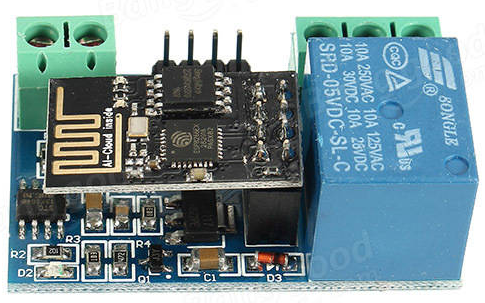
PCB e piedinatura:

Schema modifica scheda ESP-01 con relay:

il circuito originale prevede un microntrollore (8051 clone, stc15f104) che gira un programma di controllo in grado di connettersi ad un cloud proprietario attraverso lo ESP-01 controllato con comandi AT. Per poter programmare lo ESP-01, tramite il connettore J3, ed anche il relay tramite la R3, il microcontrollore deve essere rimosso dalla scheda.
La programmazione avviene come al solito da ambiente IDE, ponendo a zero il GPIO 0 durante il reset. CH_PD deve essere tenuto a 3.3V (R1 10K).

Currently employed as network architect, always Internet working man, real C/C++ programmer in the past, network and Unix system engineer as needed, HAM Radio enthusiast (former IW0RDI, now IW0HDV), aeromodeller (a person who builds and flies model airplanes) since 1976 (ex FAI10655).
http://www.montefusco.com - https://github.com/amontefusco - https://github.com/IW0HDV - andrew@montefusco.com
Links
- ESP8266 community wiki
- Datasheet
- ESP-12 first activation
- HowTo ESP8266
- Getting started with MicroPython on the ESP8266
- Programming the ESP8266-12E Using Arduino Software/IDE
- Simba
- Programmare l'ESP8266: ovvero Arduino con il WiFi a meno di €2
- Universal Telegram Bot Library
- Modelli disponibili
- HomeKitLight
- ESP8266 Arduino Core Reference Digital and Analog IO