Practical study about a power supply with supercap backup features
On the market there are a lot of devices useful to solve this kind of issue, very common in the MCU or CPU systems where a sudden power loss can corrupt the file system or create other problems. The current supercaps are cheap and more reliable than a battery of any chemistry. The system must be advised when the power goes down and it just requires a bunch of seconds to execute the normal shutdown procedure that syncs all the storage devices and detaches correctly all the peripherals. Let's explain a practical example where a 5V power supply is available to power up a 3.3V device. We need a regulator that supplies the device in usual operation and a backup source that stores enough energy to give to the system the time for a graceful shutdown. If the regulators is capable to work correctly in a wide range of input voltages, we can also use small supercaps.
Power regulator
Just because this issue is so common, it's easy to find a device that fits all our needs. Searching among the Texas Instruments documentation and developing tools (see link section for references) we found the TPS6302x buck-boost regulators family. The TPS63021 is the fixed voltage version.
As TI wrote on the datasheet:
The TPS6302x are high efficiency, low quiescent current, non-inverting buck-boost converters suitable for applications that need a regulated output voltage from an input supply that can be higher, lower or equal to the output voltage. Output currents can go as high as 2 A in boost mode and as high as 4 A in buck mode.
As the different application examples highlights, it has been designed to be used to get the maximum when batteries or super capacitors can still deliver enough power but with a voltage lower than required by the system, with high efficiency both at light load and at lower input voltage.
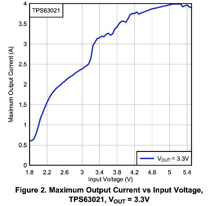
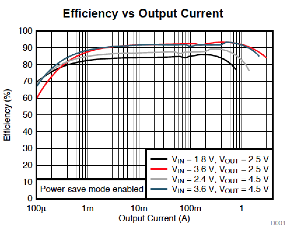
As shown in the graph below, it can still deliver an output current of 500mA @ 3.3V with an input voltage of 1.8V, draining a lot more energy from the backup source compared to buck only power regulator.
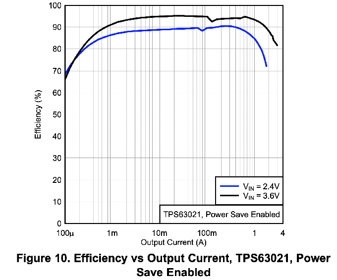
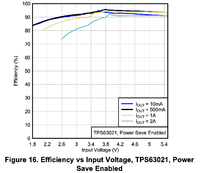
It has a good efficiency also when used in normal operation
Considering a market price of €1.2 @ 1000, small footprint and minimal BOM count, it can definitely be the right candidate.
Super capacitor
The market released a wide range of supercaps in the last few years. Differently from the ones available in the past, they have very low current leakage and ESR, allowing their use also in battery powered systems that require hundreds of mA. See also this study. Just as an example, searching in the Digikey catalog for supercaps in the 1F to 5F range, @ 5V with an ESR lower than 200mOhm, there are about 30 items, with a cost in a €1.2/€8.9 range @ 1000. The cost is influenced also by the reliability of the device, measured as the time it can resist at a given temperature. A good balance among price, reliability, features and availability, can be found in the AVX SCM series.
Schematic
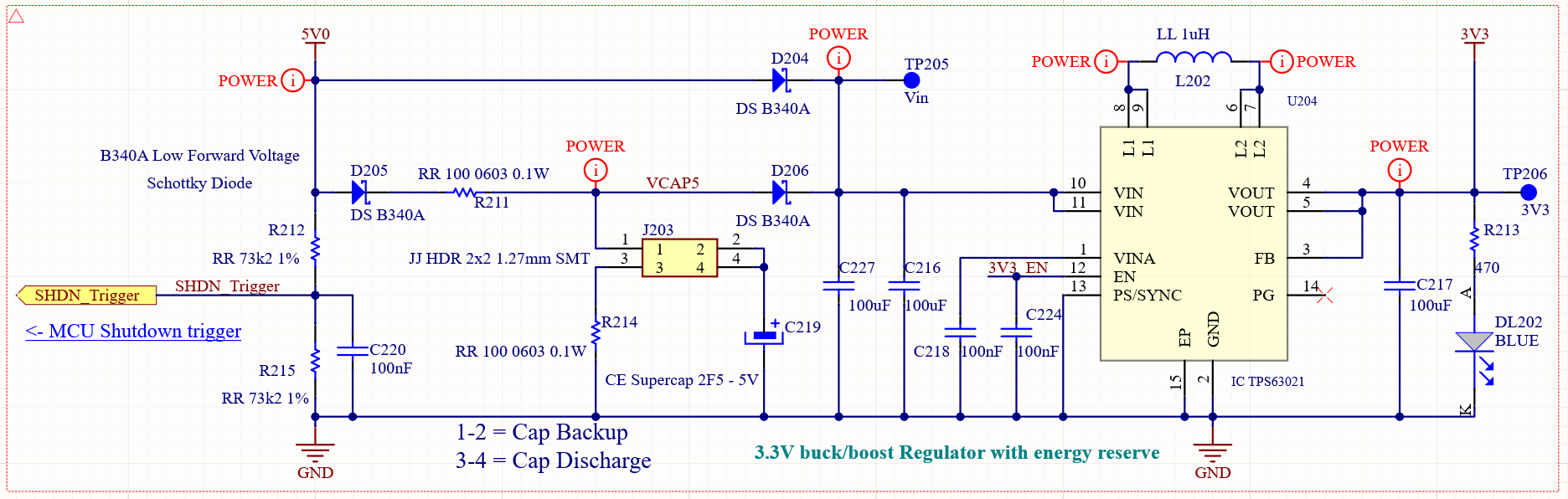
Putting the previous consideration all together, we have the schematic below:
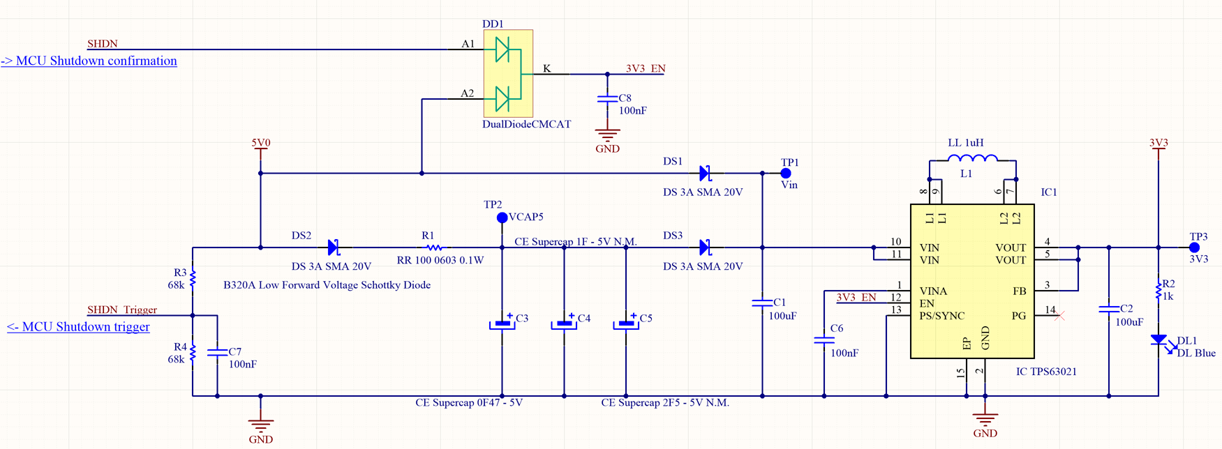
Using a footprint as shown below, we can choose a supercap between 0.47uF to 2.5F according to our needs.

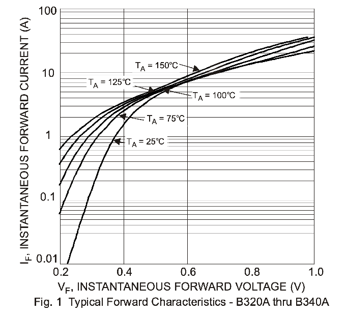
Let's make some simple estimations on the performances. The input voltage is given at 5V. If the 5V power supply is under our control it can also be enhanced to 5.2V, compatible with all the other devices and compensating some voltage losses. In order to reduce the power losses it's strictly advised to use a very low forward voltage Schottky diode, even if its current limit is higher than we need. The graph below shows the Vf of the Diodes B320A rectifier vs If.
The resistor R1 limits the initial current to 50mA. This increases the time needed for the supercap to be fully charged but avoids a quasi-short circuit when it's empty. When the supercap is fully charged the current across DS2 is extremely low, as well as its Vf. At VCAP5 test point we can therefore consider a voltage very close to 5V, but in any case lower then 5V0, enabling the regulator to be powered by the main supply in normal conditions. As soon as the main power goes off, the voltage at VCAP5 TP2 becomes higher then 5V0, DS3 goes in conduction state powering up IC1 without glitches. DS1 and DS2 avoid the current to be wasted backward.
Energy available
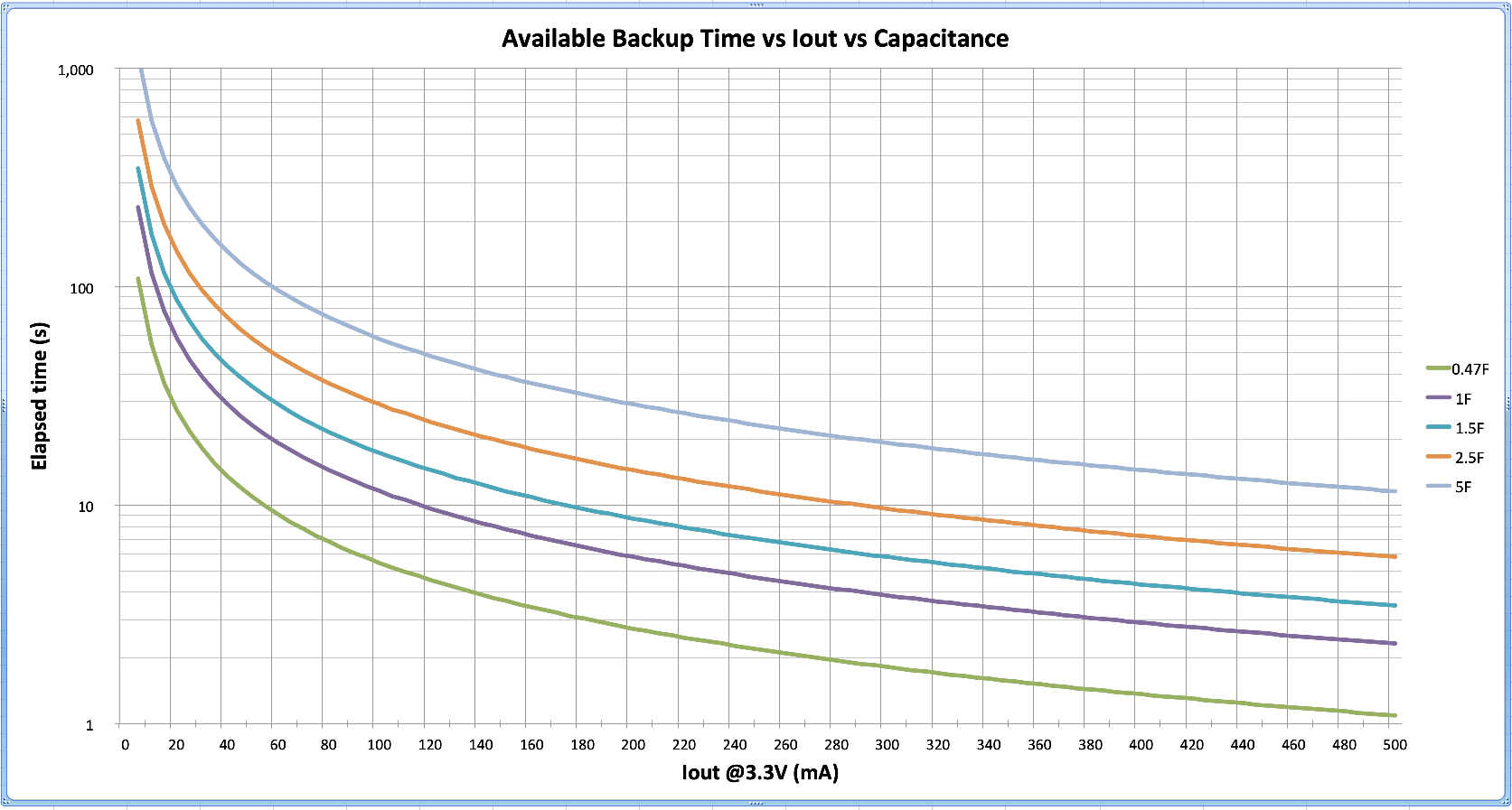
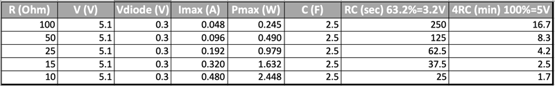
We know that the energy available from the supercap is E=1/2 C ΔV^2 in Joule = W * s. If we consider a Vf of 0.2V across DS3 and a lower voltage limit of 1.8V for IC1, we have ΔV = 4.8 - 1.8 = 3V so, an energy in the range 2.2 watt per 1 second with a 0.47F capacitor to 22.5 watt per 1 second for a 5F capacitor at the IC1 input. In the worst case of an 85% efficiency we have about 2 to 20Ws @ 3.3V out.
In order to select the right capacitor for our own system, in the graph below is depicted a rough estimation of the time available to the CPU for shutdown in different conditions of current consumption and capacitance.
Shutdown trigger
In order to trigger the regular shutdown on the system, the divider realized with R3 and R4 resistors adapt the 5V power supply to a level compatible with the CPU/MCU. The SHDN_Trigger signal can be sent to a Schmitt triggered digital input, to an analog comparator, to an ADC input or whatever on the device is capable to trigger an high priority interrupt. This must run a safe procedure according to the peripherals involved when the input voltage drops below a given threshold.
Because the supercap keeps the 3.3V high for a long time with no or light load, the device could be not able to recognize the changing in the power supply when 5V0 power returns, failing the restart. To solve this issue the DD1 dual diode has been added to control the enable input of the regulator. The regulator is enabled when 5V0 power supply is up OR when SHDN out of the MCU is high. If 5V0 goes down, the 3V3 regulator keeps working, thanks to the SHDN signal, until the MCU is completely off. When the 5V0 returns, the enable pin rise high, the 3V3 power supply returns good as well and the MCU is restarted. An issue is still on. If the 5V0 returns while the SHDN is still high, meanwhile the shutdown procedure is executing, the regulator, as well as the MCU, is no more able to recognize the changing. The micro-interruptions can be bypassed adding at software level a slight delay before starting safe procedure.
A possible solution to this issue, not yet tested, could be modifying the schematic as shown below:
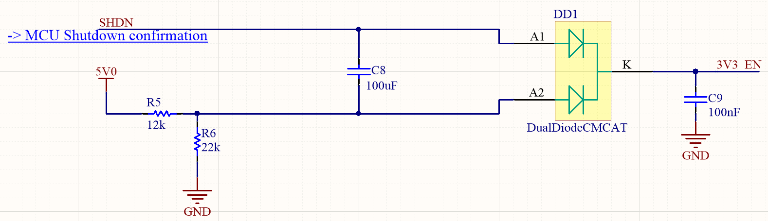
If 5V0 supply returns while the software shutdown procedure is running, C8 capacitor has the same voltage at both terminals, so it's empty. When SHDN goes low, it grounds C8 that starts charging with a time constant of about 1s. During this time 3V3_EN is low as well switching off the 3V3 power supply for a while. When C8 is full charged again, the enable is high and everything runs fine again after an hard reset.
Some sort of debouncing can be added both at hardware (C7) and software level in order to avoid false alarms.
Update
After a long break due to the lockdown, thanks to ACME Sytems and the persons of Roberto Asquini and Antonio Galea, we have eventually been able to test the above theory in the real world. We have deeply tested all the possible fault combinations we could imagine.
The final schematic is similar to that shown above, the load is about 150mA @5V on a ACME Sytems Acqua SoM. The Supercap is a 2.5F @6V AVX SCM series.
The very first test is without any software modification, just to check if the maximum available energy stored agrees with the theory.
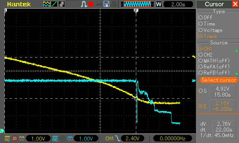
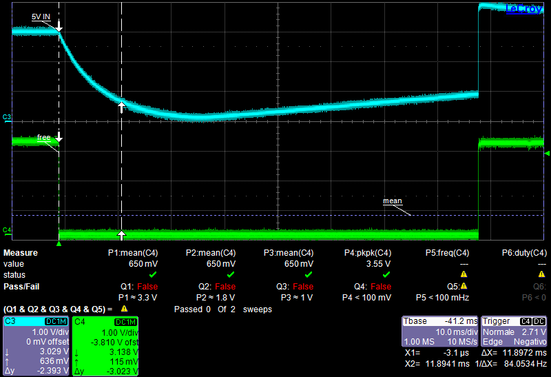
The yellow trace is the Vcap, the light blue one is 3.3V after buck-boost regulator. After more than 20s since the main power failure the regulator switches off, when the Vcap goes down to 2.16V, according with the TPS63021 data sheet (0.3V dropout on the schottky diode). There is a little rebound when the load drops down because there is no more dropout on diode and the voltage goes again above the treshold. When the regulator is off the Vcap remain at 2V because of the lack of load. To be noted that the discharge curve is almost linear because the converter gets a constant power to supply its load, at the contrary of the theoretical graph above at a constant resistance load. When the Vcap goes below 3.3V the regulator switches to boost mode from buck mode until the treshold and the discharge speed increases a bit because the efficiency is lower.
The first goal is achieved, the available time is according to the calculations.
The second test requires that the SHDN trigger GPIO is configured as Power OFF Key in the systemd. When the main power goes down the regular shutdown procedure is started saving all the files and active processings.
Because of an Acqua CPU particular behavior, the SHDN GPIO doesn't come again to high level when the power is back. This requires a little hardware add-on to start a short wakeup pulse when 5V0 returns.
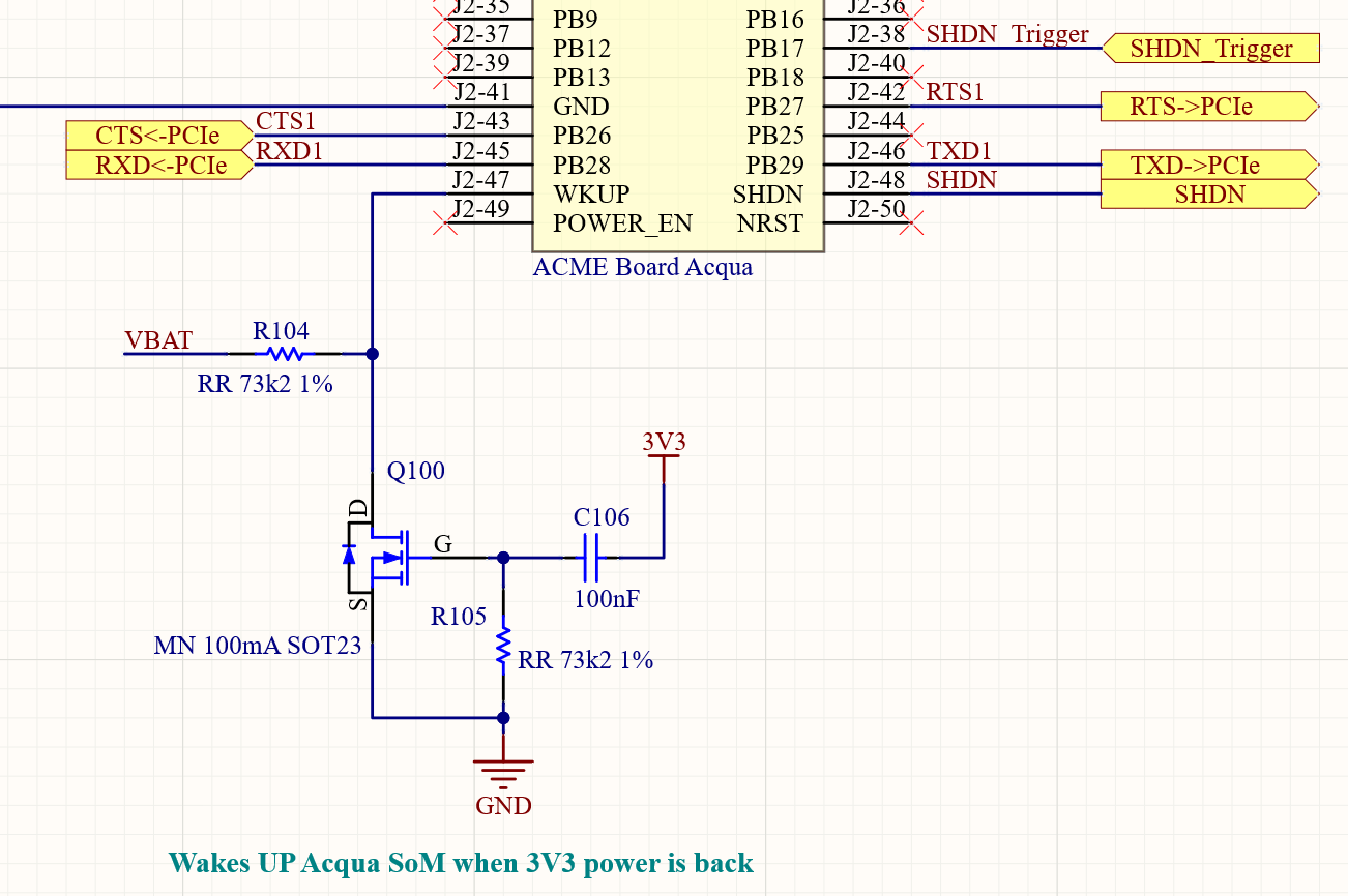
This triggers the WKUP signal starting a new boot.
Also the second goal is achieved. The shutdown procedure requires just a bunch of seconds, leaving enough energy into the supercap to keep Vbat high for RTC.
Another test is to check the behavior if the 5V0 comes back while the shutdown procedure is still runnning. The schematic above has been a little bit modified.
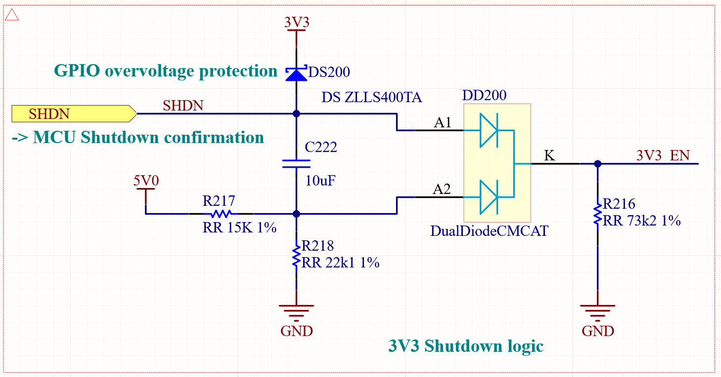
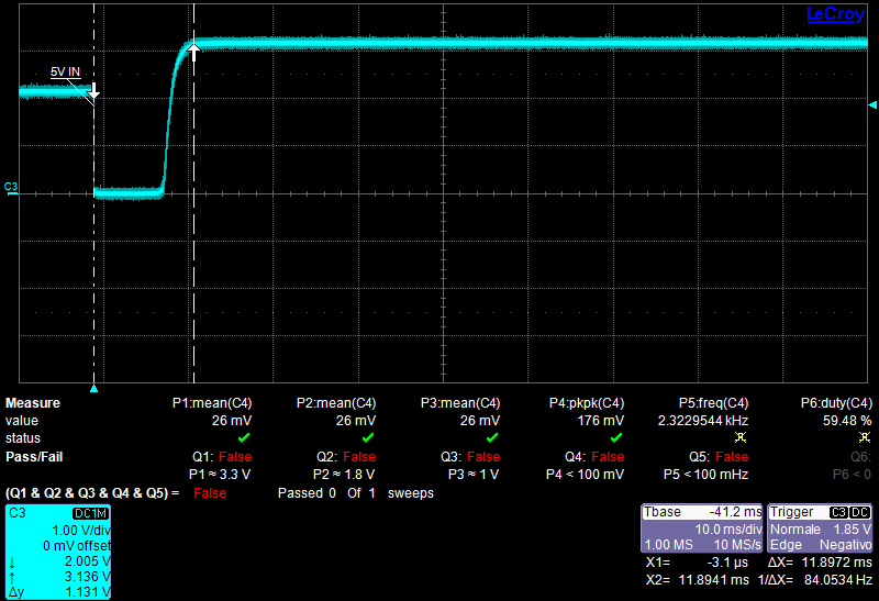
The C222 capacitor is reduced to 10uF from 100uF to set the correct pulse duration. A protection diode is added to prevent overvoltage to the SHDN GPIO.
The graph above shows how when the 5V0 is back, the C222 residual charge is added to 3.3V raising the voltage at a critical level. The schottky DS200 diode reduces this level to 3.3V plus its dropout.
Adding a software debounce time to the SHDN trigger GPIO driver, avoids the immediate starting of the shutdown procedure bypassing any micro-power outages.
The final schematics of the power supply is the following.
A possible hardware modification could be done on the supercap charge circuit. With the one shown in the schematics above the current is limited to a safe level but the charge time is more then 15 minutes, to much if the power outage is repeated frequently in a short time. To short that time a lower resistance value must be choosen, keeping attention to the maximum available current and the resistor power dissipation.
A good compromise could be the use of a 15Ω 2W resistor in a 2512 package that reduces the full charge time to 2.5 minutes.
There are many suggestions on the Net about alternative possible solutions. One of the most interesting is the Application Report SLVA920 by Texas Instrument. That allows a fast charge and also avoids the need of the D205 diode, without its dropout the available charge voltage is raised as well as the total energy reserve.
The backup system described here demonstrates a robust behavior on most of the possible outage situations, even with a relatively simple circuit and a little energy reserve.
Links
- Texas WEBENCH® Power Designer project
- TPS6302x data sheet
- Supercapacitor Backup Power Supply With Active Cell Balancing
- AVX supercaps SCM series
- Diodes B320A low forward voltage Schottky barrier rectifier
- Application Report SLVA920 by Texas Instrument
- ACME Sytems Acqua SoM

He deals with electronic design and embedded system firmware for Robotics and industrial and civil applications, as well as technical disclosure on the internet.
http://www.guiott.com - https://github.com/guiott - guido@guiott.com